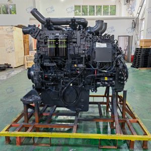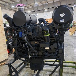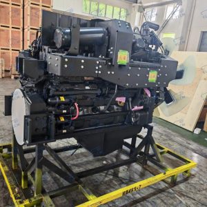

Sensors on an excavator are the feedback layer between the hydraulic, engine, and electrical systems and the machine controller. The main types of sensors used in excavator parts are pressure, temperature, speed and rotation, position and angle, level, and emissions sensors. Each type tells the control system whether a circuit, fluid, or moving component is operating within the expected range. That feedback protects the engine, regulates hydraulic flow, supports emissions control, and gives the operator an early warning before a minor fault becomes a major failure. For parts buyers, the task is not only to recognize these sensor types, but to match the signal, connector, mounting, and part number to the machine.
What Sensors Do on an Excavator
A sensor converts a physical condition into an electrical signal the controller can read. On excavators, the most common inputs are pressure, temperature, speed, position, level, and emissions conditions. A pressure sensor may report hydraulic pressure as a changing voltage or current signal, while a pressure switch reports only an open or closed state. The controller uses these inputs to limit pump load, adjust fuel delivery, trigger regeneration, or warn the operator. That is why a replacement sensor must match more than the thread and connector. It must match the output characteristic the controller expects. Many analog sensors on excavators produce a ratiometric voltage signal, often about 0.5 to 4.5 V, while some industrial systems use 4 to 20 mA current loops. Hall effect sensors are common for speed and position because they detect rotation without direct contact.
| Sensor type | Typical measured input | Main function on the machine | Key replacement detail |
|---|---|---|---|
| Pressure sensor or transmitter | Hydraulic, pilot, fuel, boost, DPF pressure | Pump control, overload protection, emissions | Pressure range, thread, connector, output |
| Temperature sensor | Coolant, hydraulic oil, air, fuel, exhaust | Warmup, cooling, derating, aftertreatment | Resistance curve, thread, connector |
| Speed or rotation sensor | Engine, turbo, travel, swing, fan speed | Injection timing, motion control, overspeed protection | Mounting gap, target, connector |
| Position or angle sensor | Joystick, throttle, pedal, boom, bucket, EGR | Operator input, motion control, valve position | Rotation, PWM or voltage, connector |
| Level sensor or switch | Fuel, oil, coolant, DEF | Operator warning, protection, DEF dosing | Length, float type, resistance or switch logic |
| Emissions or gas sensor | NOx, O2, exhaust temperature, DEF quality | Regeneration, emission control | Engine family, part number, software compatibility |
Pressure and Temperature Sensors
Pressure sensors are among the most frequently replaced sensors on a hydraulic excavator. They appear at the main hydraulic pump, pilot control circuit, implement circuits, swing or travel circuits, engine oil or fuel rail, and diesel particulate filter differential pressure lines. The controller uses these readings to manage pump flow, detect overpressure, and protect the engine during load changes. A failing pressure sensor can produce slow hydraulic response, unstable pump control, or a false overload code.
Temperature sensors protect the engine, hydraulic system, and aftertreatment system. Common locations include coolant, hydraulic oil, intake air, fuel, exhaust gas, and DEF. Many are negative temperature coefficient thermistors, which change resistance as temperature changes. The controller uses this data for warmup, cooling fan operation, derating, and emission control. A temperature sensor that drifts out of calibration may cause false high temperature alarms, cold start problems, or unnecessary derating.
Speed, Position, and Level Sensors
Speed and rotation sensors detect engine speed, camshaft position, turbo speed, travel motor speed, swing speed, or fan speed. Inductive or Hall effect sensors read a target wheel, gear teeth, or reluctor ring. The engine controller uses speed signals for injection timing, idle control, and overspeed protection. A weak or intermittent speed signal can cause no start, rough idle, or loss of travel feedback.
Position and angle sensors measure the movement of a control input or a machine structure. Examples include joystick lever position, throttle dial position, accelerator pedal angle, boom and bucket angle, EGR valve position, and hydrostatic pump swash plate angle. They may be potentiometer, Hall effect rotary, or PWM output sensors. The controller compares the commanded position with the reported position, so a faulty position sensor often appears as a function that does not respond in proportion to the operator input.
Level sensors and switches monitor fuel, hydraulic oil, coolant, engine oil, and DEF. Some use a float and variable resistor, some use reed switches at fixed points, and some DEF systems use ultrasonic or capacitive sensors. Level information protects against air entering the fuel system, low oil operation, or running out of DEF.
Emissions and System Monitoring Sensors
Modern excavators add a separate class of sensors for emission control and system monitoring. These include NOx sensors, oxygen sensors, exhaust temperature sensors, diesel particulate filter pressure sensors, DEF level and quality sensors, and ammonia sensors on some selective catalytic reduction systems. The engine controller uses them to manage regeneration and DEF dosing while keeping emissions within the expected operating window.
These sensors are often engine family specific and may require correct installation orientation, clean connectors, and compatible control software. Mixing a mechanically similar sensor from another engine family can trigger persistent fault codes even when the part looks identical. Before replacing an emissions sensor, confirm the part number, engine serial number, and any software or calibration requirement with the supplier or service documentation.
How Sensor Failure Shows Up in the Machine
Many sensor failures first appear as an intermittent fault code rather than a complete machine shutdown. The controller may ignore the signal, enter a fixed default value, or derate the system. Operators may notice slow hydraulic response, high fuel use, black smoke, reduced power, repeated regeneration, false gauge readings, or a warning that does not clear.
Because the same symptom can come from the sensor, its wiring, a connector, or the component being measured, the best first check is to read the live data and compare it with the expected range. For example, a coolant temperature reading that jumps to an impossible value while the engine is cold points to a circuit or sensor problem, not actual overheating. This avoids replacing a good sensor and leaving a damaged harness in place.
Reading a Sensor Part Number and Specification
Excavator sensors are normally identified by the original equipment part number, the machine model and serial number, and sometimes the engine serial number. Part number alone is the best starting point, but it is not always enough when a design has been superseded or when the same connector is used on several sensors with different ranges.
Confirm the output type: voltage, current, PWM, frequency, or switch. Confirm the supply voltage, connector shape and pinout, thread size or mounting pattern, and the operating range or calibration. Ask whether the replacement requires a calibration procedure or controller update. For aftermarket parts, request the manufacturer part number and a photo of the label, connector, and mounting face before shipment.
Sensor identification is part of a broader parts acceptance process, not a one step visual match. <What Really Matters When Sourcing Excavator Parts: A Breakdown of Critical Components> covers how component details and verification steps reduce the risk of buying the wrong part.
Sourcing Sensors Without Buying the Wrong Part
Use the old sensor as a reference whenever possible. Record the part number, wire colors, connector orientation, mounting thread, and any visible marking before removing it. Compare those details with the supplier’s photo and data sheet. For critical engine or emissions sensors, prefer the original equipment part number or a manufacturer-approved aftermarket replacement with a clear cross reference. For less critical switches and level senders, aftermarket parts may be acceptable if the electrical output and mechanical fit are confirmed. Ask the supplier how the part is tested, whether it carries a warranty, and how returns are handled if the fault code does not clear. A low price does not help if the sensor sends the wrong signal and the controller continues to derate the machine.
Supplier screening becomes especially important when a sensor is needed quickly and the failure code must not return. <Choosing Reliable Excavator Parts Suppliers: A China Guide> covers how to evaluate supplier reliability and parts consistency before committing an order.
Confirm the Right Sensor Before You Order
Before ordering, send the machine model and serial number, the old sensor part number or clear label photos, connector and mounting photos, and the active fault code. Send these details to Shanghai Yanli Construction Machinery Co., Ltd. at sales@sh-yshuo.com or +86-21-55800172, and we can help confirm the matching sensor, recommend an OEM or aftermarket supply option, and check compatibility before shipment.
FAQ
Are excavator sensors interchangeable between brands?
No. Even when connectors look similar, sensors differ by signal type, voltage range, mounting thread, and calibration. A sensor with the same physical thread may use a different output curve and cause a fault code or derating. Some generic pressure or temperature switches can be matched carefully, but engine, emissions, and pump control sensors should be confirmed by part number, machine serial, and output specification.
Can I replace a failed sensor with an aftermarket part?
Yes, when the electrical output, range, connector, and mounting match and the replacement is from a manufacturer with a clear cross reference. Aftermarket parts are most suitable for general pressure, temperature, level, and proximity sensors. For emissions, engine timing, or pump control sensors, verify that the supplier has tested the replacement on the same or equivalent machine family. Ask for the manufacturer part number and warranty before buying.
How do I confirm the correct sensor before ordering?
Start with the original part number, machine model, serial number, and engine serial number. Add the wire colors, connector shape, thread size, and a photo of the label and mounting face. Then compare the supplier’s data sheet for supply voltage, output type, and range. If the original number has been superseded, ask for the chain of substitution and confirm that the controller calibration is still valid.
Why does the monitor show a sensor code after replacement?
The new part may have the correct thread but the wrong output characteristic, or the connector pins may be dirty, miswired, or not fully seated. Some sensors also require a calibration or controller reset after installation. Check the live data first. If the reading is fixed, out of range, or unstable, inspect the harness and connector before assuming the new sensor is faulty.
Do sensors need to be calibrated after installation?
Some do, especially emissions sensors, EGR position sensors, or sensors that require a learned zero point. Others are plug and play once the part number and output match. The service manual or supplier should state whether a calibration step is needed. If the machine does not provide a calibration function, a sensor that requires one will not operate correctly.
If you’re interested, check out these related articles:
Sourcing John Deere 120C Excavator Parts: A Practical Guide
Locating an Excavator Hydraulic Pump: A Sourcing Guide