A mismatched hydraulic pump coupling can cause vibration damage, premature seal failure, and unplanned downtime that costs far more than the coupling itself. For excavators, loaders, and mining equipment operating in demanding conditions across Central Asia, Africa, and Southeast Asia, selecting the correct coupling is not a minor procurement detail but a decision that directly affects machine availability and maintenance costs.
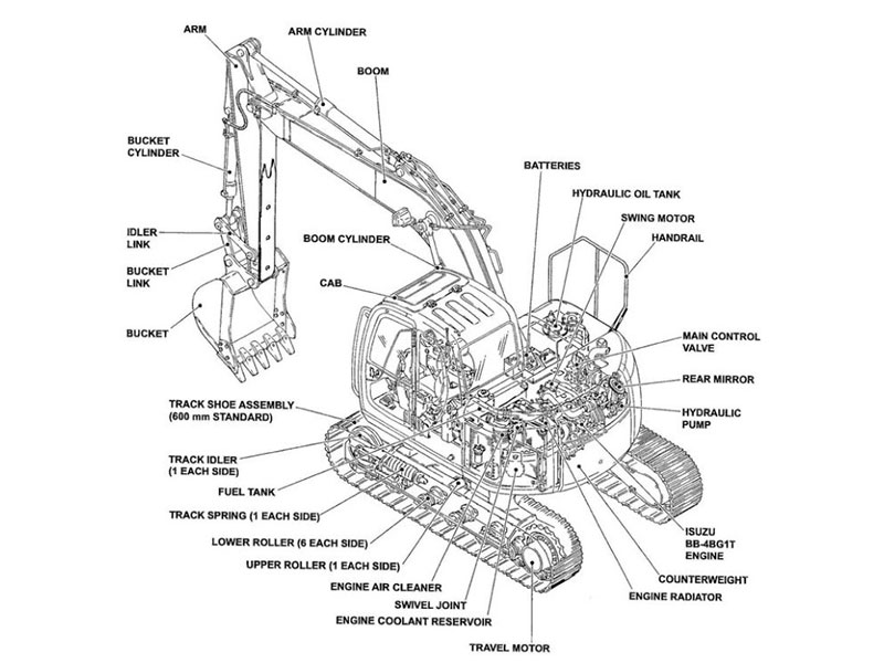
Hydraulic pump couplings connect the prime mover (engine or electric motor) to the hydraulic pump, transmitting torque while accommodating misalignment and absorbing shock loads. The coupling must match the pump’s torque requirements, shaft dimensions, and operating environment. Getting this wrong leads to coupling failures that can damage both the pump and the power source, turning a relatively inexpensive component into a costly repair event.
This guide covers the key parameters for hydraulic pump coupling selection, explains the differences between coupling types used in construction and mining machinery, and provides practical steps for matching couplings to specific equipment requirements.
 ## What Does a Hydraulic Pump Coupling Actually Do
The hydraulic pump coupling serves three primary functions: torque transmission, misalignment compensation, and vibration damping. Each function matters for equipment longevity.
Torque transmission is the obvious role. The coupling transfers rotational power from the engine flywheel or motor shaft to the hydraulic pump input shaft. The coupling must handle both continuous operating torque and peak torque during sudden load changes, such as when an excavator bucket hits hard material.
Misalignment compensation addresses the reality that perfect shaft alignment is rarely achieved or maintained in field conditions. Angular misalignment (shafts at a slight angle), parallel misalignment (shafts offset but parallel), and axial displacement (shafts moving closer or farther apart) all occur during operation due to thermal expansion, frame flex, and mounting tolerances. A properly selected coupling absorbs these movements without transmitting damaging forces to pump bearings or seals.
Vibration damping protects both the pump and the power source from torsional vibrations. Diesel engines produce inherent torsional pulses, and hydraulic systems generate pressure spikes during valve shifts. The coupling’s flexible element absorbs these oscillations, reducing fatigue stress on connected components.
I have seen cases where operators replaced pumps repeatedly without addressing coupling wear, only to find that a degraded coupling element was allowing excessive vibration to destroy pump bearings within months of each replacement. The coupling is often the overlooked component in hydraulic system troubleshooting.
Hydraulic Pump Coupling Types for Construction Equipment
Different coupling designs suit different applications. Understanding the main types helps narrow the selection before matching specific parameters.
| Coupling Type | Flexible Element | Misalignment Capacity | Typical Application |
|---|---|---|---|
| Jaw (Spider) | Elastomer insert | Low to moderate | General purpose, moderate loads |
| Rubber Element | Bonded rubber blocks | Moderate | High vibration damping needs |
| Disc | Metal or composite discs | Low angular, moderate axial | High speed, precise alignment |
| Gear | Steel teeth with lubrication | High | Heavy duty, high torque |
| Centaflex | Rubber segments | Moderate to high | Engine to pump, high torsional damping |
Jaw couplings use a star-shaped elastomer insert (spider) between two hubs. They are common in excavator hydraulic components because of their simple construction, easy replacement of the spider element, and reasonable cost. The spider material (urethane, rubber, or Hytrel) affects hardness, temperature range, and damping characteristics.
Rubber element couplings use bonded rubber blocks or segments that provide excellent vibration isolation. These work well when the diesel engine produces significant torsional vibration or when the hydraulic system experiences frequent pressure spikes.
Disc couplings use thin metal or composite discs that flex to accommodate misalignment. They transmit torque with zero backlash, making them suitable for applications requiring precise positioning. However, they offer less vibration damping than elastomer types.
Gear couplings consist of two hubs with external teeth that engage with internal teeth on a sleeve. They handle high torque and significant misalignment but require lubrication and periodic maintenance. Mining equipment with very high torque requirements often uses gear couplings.
Centaflex-type couplings are specifically designed for engine-to-pump connections. They use rubber segments arranged in a pattern that provides high torsional flexibility while maintaining torque capacity. These are common in Komatsu and Cat equipment where the hydraulic pump mounts directly to the engine flywheel housing.
Key Parameters for Hydraulic Pump Coupling Selection
Selecting the right coupling requires matching several parameters to your specific application. Missing any one of these can lead to premature failure.
Torque capacity is the starting point. You need to know the pump’s maximum torque requirement, which depends on pump displacement and maximum operating pressure. The formula is straightforward: Torque (Nm) = Displacement (cc/rev) × Pressure (bar) / 62.8. Apply a service factor of 1.5 to 2.5 depending on load characteristics. Excavators with frequent shock loads need higher service factors than equipment with steady loads.
Shaft dimensions must match exactly. Measure the pump input shaft diameter, length, and keyway dimensions. Measure the engine flywheel pilot bore or motor shaft dimensions. The coupling hubs must fit both shafts with proper clearance for keys and set screws.
Speed rating matters for high-RPM applications. The coupling must be rated for the maximum operating speed with a safety margin. Centrifugal forces at high speed can stress the flexible element and hub connections.
Misalignment capacity should match realistic installation and operating conditions. If your equipment operates in conditions where frame flex is significant or where precise alignment is difficult to achieve, select a coupling with higher misalignment tolerance.
Temperature range affects elastomer life. Standard rubber elements work well from -20°C to +80°C. Equipment operating in extreme cold (Siberian mining operations) or extreme heat (Middle Eastern construction sites) needs couplings with appropriate elastomer compounds.
Bore and keyway standards vary by manufacturer and region. Japanese equipment often uses metric dimensions with JIS keyway standards. American equipment typically uses inch dimensions with ANSI keyways. European equipment follows DIN standards. Confirm compatibility before ordering.
How to Identify the Correct Replacement Coupling
When replacing a worn coupling, start by identifying the original part. This is more reliable than measuring and hoping to find a match.
Check the equipment parts manual first. The coupling part number should be listed in the hydraulic pump mounting section or the engine accessory drive section. For Komatsu equipment, the coupling is often listed as part of the pump drive assembly. For Caterpillar machines, look in the power train section.
If the parts manual is unavailable, examine the existing coupling for markings. Many couplings have part numbers stamped or molded into the hubs or flexible element. Centaflex couplings typically have a size designation (CF-A-22, CF-H-140, etc.) that indicates torque capacity and dimensional series.
Photograph the coupling from multiple angles before removal. Measure overall length, hub outer diameters, bore diameters, and keyway dimensions. Count the number of teeth or segments if applicable. These details help suppliers identify the correct replacement.
Cross-reference databases exist for common coupling types. A Komatsu coupling can often be matched to an equivalent aftermarket part using the OEM part number. The key is ensuring the replacement meets or exceeds the original specifications for torque, speed, and misalignment capacity.
If you are sourcing a coupling for equipment where the original specification is unknown, send the pump model number and engine model number to your supplier. Experienced suppliers can identify the correct coupling from equipment application data.
 ## Common Hydraulic Pump Coupling Sizes in Construction Equipment
Hydraulic pump couplings follow size standards that correlate with torque capacity. Knowing the common sizes helps when specifying replacements.
| Size Designation | Approximate Torque (Nm) | Typical Equipment Class |
|---|---|---|
| CF-A-22 / Size 22 | 220 | Mini excavators, small loaders |
| CF-A-28 / Size 28 | 500 | 6-10 ton excavators |
| CF-H-80 / Size 80 | 800 | 15-20 ton excavators |
| CF-H-140 / Size 140 | 1400 | 25-35 ton excavators |
| CF-H-240 / Size 240 | 2400 | 40-50 ton excavators, large loaders |
These are approximate ranges. Actual torque ratings vary by manufacturer and coupling design. The size designation typically indicates the torque capacity in a standardized series, but always verify the specific rating for the coupling you are considering.
For excavators in the 20-30 ton class, which covers popular models like the Komatsu PC200, Hitachi ZX200, and Cat 320, the coupling size is typically in the 80-140 range. Larger mining excavators and wheel loaders use proportionally larger couplings.
The flexible element (spider, rubber segments, or disc pack) is usually the wear item. Many coupling designs allow replacing just the flexible element without removing the hubs from the shafts. This reduces downtime and cost for routine maintenance.
Installation and Alignment Considerations
Proper installation determines coupling life as much as proper selection. Even the best coupling fails quickly if installed incorrectly.
Shaft preparation matters. Clean both shafts thoroughly. Remove any rust, old sealant, or debris. Check for damage to keyways and shaft surfaces. A damaged keyway can allow the hub to shift under load, leading to vibration and eventual failure.
Hub installation requires attention to fit. The hub bore should have a slight interference fit or close sliding fit on the shaft. Loose fits allow fretting corrosion and eventual hub cracking. Use the manufacturer’s recommended installation method, whether that involves heating the hub, using hydraulic installation tools, or simply pressing with appropriate force.
Alignment verification should happen even though the coupling accommodates misalignment. The coupling’s misalignment capacity is for absorbing unavoidable movement during operation, not for compensating for sloppy installation. Use a straightedge and feeler gauges or a dial indicator to check alignment. Bring angular and parallel misalignment within the coupling’s rated capacity, preferably to half the rated capacity for longer life.
Torque specifications for hub fasteners (set screws, clamping bolts) must be followed. Under-torqued fasteners allow slippage. Over-torqued fasteners can crack hubs or strip threads.
Flexible element installation varies by design. For jaw couplings, the spider simply drops between the hubs. For Centaflex types, the rubber segments must be installed in the correct orientation with proper preload. Follow the manufacturer’s instructions exactly.
 ## Signs of Hydraulic Pump Coupling Wear
Recognizing coupling wear before complete failure prevents secondary damage to pumps and engines.
Vibration increase is often the first sign. As the flexible element wears, it loses its damping capacity and may develop clearance that allows play between hubs. This shows up as increased vibration at the pump mounting or in the hydraulic lines.
Noise changes accompany wear. A worn jaw coupling may produce a rattling or knocking sound as the spider develops clearance. Gear couplings with worn teeth produce a grinding noise.
Rubber debris around the coupling area indicates element deterioration. Check during routine inspections. Finding rubber particles or chunks means the flexible element is breaking down.
Misalignment symptoms in the pump (such as premature seal leakage or bearing noise) can indicate that the coupling is no longer absorbing misalignment effectively. A hardened or cracked flexible element loses its flexibility.
Visual inspection during scheduled maintenance should include checking the flexible element for cracks, chunks missing, hardening, or deformation. Check hub-to-shaft fit by attempting to move the hub on the shaft. Any movement indicates a problem.
Coupling inspection should be part of every 500-hour service interval. Replacement of the flexible element is typically recommended every 2000-4000 hours depending on operating conditions, but actual life varies significantly with load severity and alignment quality.
OEM Versus Aftermarket Hydraulic Pump Couplings
The choice between OEM and aftermarket couplings involves tradeoffs in cost, availability, and risk.
OEM couplings guarantee fitment and specification compliance. The coupling will match the original equipment design intent. For warranty considerations or when equipment operates in critical applications where any risk of incompatibility is unacceptable, OEM is the safe choice. The downside is cost (often 2-3 times aftermarket prices) and lead time (OEM parts may have long delivery times, especially for older equipment models).
Quality aftermarket couplings from reputable manufacturers can match OEM specifications at lower cost. The key is verifying that the aftermarket coupling meets the same torque rating, dimensional specifications, and material standards as the original. Reputable aftermarket suppliers provide specification sheets and can cross-reference to OEM part numbers.
Low-quality aftermarket couplings are a false economy. Couplings made from inferior materials or with loose tolerances fail prematurely and can damage expensive pumps and engines. The coupling itself is a relatively low-cost component; saving a few dollars on the coupling while risking a pump replacement makes no economic sense.
When sourcing aftermarket couplings, request material certifications and dimensional inspection reports. A supplier who cannot provide this documentation may not be controlling quality adequately.
For customers across Central Asia, Russia, Africa, and Southeast Asia, we source couplings from manufacturers in China, Japan, and the USA who meet OEM specifications. Our approach is to verify specifications against OEM requirements before offering a part as a compatible replacement. If you have a coupling requirement, send the OEM part number or equipment model and we can confirm availability and compatibility.
Matching Couplings to Specific Equipment Applications
Different equipment types have different coupling requirements based on their operating characteristics.
Excavators experience high shock loads when digging and frequent reversals of hydraulic flow. Couplings need good torsional damping and fatigue resistance. Centaflex-type rubber element couplings are common. The coupling connects the main hydraulic pump to the engine flywheel, often through a pump drive housing that may include a gear train.
Wheel loaders have similar requirements to excavators but often operate at higher average loads due to continuous pushing and lifting. The coupling may be larger relative to machine weight compared to an excavator of similar size.
Bulldozers transmit power through a torque converter and transmission for travel, but the hydraulic system for blade control uses a separate pump with its own coupling. These couplings see less severe duty than excavator main pump couplings.
Mining trucks use very large couplings for their hydraulic systems. The steering and hoist systems require high flow rates and operate continuously during loading and hauling cycles. Coupling selection must account for the high ambient temperatures common in mining operations.
Drilling equipment often requires couplings that can handle high torsional vibration from the drilling process. Specialized couplings with enhanced damping characteristics may be necessary.
For any specific application, the equipment manufacturer’s parts catalog is the authoritative source for coupling specifications. When that information is unavailable, working with a supplier who has experience with similar equipment is the next best approach.
Troubleshooting Hydraulic Pump Coupling Problems
When coupling-related problems occur, systematic troubleshooting identifies the root cause.
Repeated coupling failures in the same location suggest an underlying issue. Check alignment carefully using precision methods. Verify that the pump and engine mounts are not cracked or loose. Confirm that the coupling size is adequate for the actual operating loads, which may exceed original design assumptions if the equipment has been modified or is operating in more severe conditions than intended.
Coupling running hot indicates excessive flexing, usually from misalignment beyond the coupling’s capacity or from operating at loads that cause continuous high deflection of the flexible element. Reduce misalignment or select a coupling with higher capacity.
Flexible element failing on one side suggests angular misalignment. The element is being stressed unevenly. Realign the shafts.
Hub loosening on shaft indicates improper fit or installation. The hub bore may be worn oversize, the shaft may be undersized, or the keyway may be damaged. Inspect both components and replace as necessary. Consider using a hub with a clamping design rather than a simple bore-and-key arrangement if repeated loosening occurs.
Metallic debris in coupling area from a gear coupling indicates tooth wear. Check lubrication and alignment. Gear couplings require periodic relubrication; lack of lubrication causes rapid wear.
Getting the Right Coupling for Your Equipment
Selecting the correct hydraulic pump coupling requires knowing your equipment’s specifications, understanding the coupling types available, and matching parameters carefully. The coupling is a critical link in the power transmission chain, and getting it right prevents expensive secondary failures.
For procurement managers and maintenance teams sourcing couplings for excavators, loaders, and mining equipment, the practical path forward is to work with a supplier who understands both the equipment applications and the coupling specifications. Send your equipment model, pump part number, or existing coupling part number, and a knowledgeable supplier can identify the correct replacement and verify compatibility before shipment.
If you have a hydraulic pump coupling requirement for Komatsu, Hitachi, Caterpillar, Kobelco, or other construction and mining equipment, send the part number and quantity to sales@sh-yshuo.com or call +86-21-55800172. We can confirm stock availability, cross-reference to OEM specifications, and provide pricing for both OEM and quality aftermarket options.
Common Questions About Hydraulic Pump Couplings
How do I know when my hydraulic pump coupling needs replacement?
Increased vibration at the pump mounting area is usually the first indicator. Listen for new rattling or knocking sounds during operation. During scheduled maintenance, visually inspect the flexible element for cracks, missing chunks, hardening, or deformation. Check for rubber debris around the coupling housing. If the pump is experiencing premature seal failures or bearing wear, the coupling may no longer be absorbing misalignment effectively. Most manufacturers recommend replacing the flexible element every 2000-4000 operating hours as preventive maintenance, though actual life depends heavily on operating conditions and alignment quality.
Can I use a coupling from a different equipment brand as a replacement?
Couplings are often interchangeable across brands if the specifications match. The critical parameters are torque capacity, shaft bore dimensions (diameter, length, keyway), overall length, and bolt pattern if applicable. A coupling designed for a Komatsu PC200 may fit a Hitachi ZX200 if the pump drive arrangements are similar. However, you must verify all dimensions before assuming compatibility. The safest approach is to cross-reference using the OEM part number or to have a supplier with application experience confirm the match. If your current coupling part number is unavailable, share the equipment model and pump model with your supplier to identify alternatives.
What causes a hydraulic pump coupling to fail prematurely?
Misalignment beyond the coupling’s rated capacity is the most common cause. Even couplings designed to accommodate misalignment have limits, and exceeding those limits causes accelerated wear of the flexible element. Overloading (operating the hydraulic system at pressures or flows beyond design limits) stresses the coupling beyond its torque rating. Improper installation, including loose hub fits, incorrect torque on fasteners, or wrong flexible element orientation, leads to early failure. Environmental factors like extreme temperatures or chemical exposure can degrade elastomer elements. Finally, using a coupling that is undersized for the application guarantees short life.
Should I replace just the flexible element or the entire coupling assembly?
If the hubs are in good condition (no wear on the bore, no damage to teeth or splines, no cracks), replacing just the flexible element is cost effective and reduces downtime since the hubs can remain on the shafts. Inspect the hubs carefully during element replacement. Look for wear patterns, corrosion, or damage to the surfaces that contact the flexible element. If the hubs show significant wear or if the coupling has failed catastrophically, replace the complete assembly. For critical equipment where downtime is expensive, keeping a complete coupling assembly in stock allows faster replacement than waiting for hub inspection during a failure event.
How does operating temperature affect hydraulic pump coupling selection?
Standard rubber and urethane flexible elements are rated for approximately -20°C to +80°C. Operating outside this range accelerates degradation. In cold climates, the elastomer becomes stiff and brittle, reducing its ability to absorb vibration and accommodate misalignment. In hot climates or when the coupling is near heat sources, the elastomer softens and loses strength. For extreme temperature applications, specify couplings with appropriate elastomer compounds. Silicone-based elements handle wider temperature ranges. For very high temperature applications, consider all-metal disc couplings that eliminate elastomer temperature limitations entirely, though these provide less vibration damping. If your equipment operates in temperature extremes, mention this when requesting coupling recommendations.
Industry Standards and Data Sources Cited
AGMA (American Gear Manufacturers Association) — Coupling standards and selection guidelines
If you’re interested, check out these related articles:
Shanghai Yanli Participated in Mining & Construction Vietnam 2026 in Hanoi
Fluid Coupling: Principles and Industrial Applications in 2026